
Electric motors have had a reputation for being a mix of science and magic. So when a motor fails to operate it may not be obvious what the problem is. Knowing some basic methods and techniques along with having a few test instruments handy helps detect and diagnose problems with ease.
A Word of Warning
Some transistor equipment may be mains powered. Only qualified persons should attempt to repair mains powered equipment or equipment that contains high or hazardous voltages. High voltages can kill so be warned! Contact a licensed professional!
When an electric motor fails to start, runs intermittently or hot, or continually trips its over-current device, there my be a variety of causes. Sometimes the trouble lies within the power supply, including branch circuit conductors or a motor controller. Another possibility is that the driven load is jammed, binding or mismatched. If the motor itself has developed a fault, the fault may be a burnt wire or connection, a winding failure including insulation deterioration, or a deteriorating bearing.
A number of diagnostic tools, such as clamp-on ammeters, temperature sensors, a Megger or oscilloscope, can help illuminate the problem. Preliminary tests generally are done using the ubiquitous multimeter. This tester is capable of providing diagnostic information for all kinds of motors.

Look for obvious faults
The first step when looking at tracing any faults and testing a transistor circuit of any sort is to look for the obvious or major faults. Fortunately most faults with electronics equipment such as transistor radios are relatively major and therefore easy to find. Accordingly the first step in any fault finding is to look for the major problems.
Check the supply to the circuit: The first steps in checking the circuit are to ensure that it has power being supplied to it. This is easily done using a multimeter set to a voltage range. Measure the voltage using a multimter at the points where the supply enters the circuit board. If the multimeter indicates that there is no supply voltage then there can be a number of possibilities to investigate:
Battery could be flat if the equipment is battery powered
If the transistor equipment is battery powered, the battery could have been left in for many months and corroded the battery compartment. Check for this and if there are signs of leakage then clean and remove all signs of corrosion being careful not to touch any of the residue.
On-off switch faulty. This can be checked by disconnecting any power source and checking for continuity across the switch
Corroded connector. One common problem is that connectors become corroded with time and connections can become very poor, especially of the equipment has not been used for some time. To overcome this it can help to unplug and then re-mate the connector.
Check for any broken wiring that would prevent the power reaching the circuit board.
Check the outputs from the board: In the same way that broken connections may exist for the power line, the same may be true of the outputs from the board. Again it is worth checking any connectors that may have corroded or oxidised with time, and check for any broken connections.
Check the inputs to the circuit: Likewise, if the signal inputs are not reaching the board then it will not be able to perform. Again any switches, and connectors along with any broken wires should be checked. Often a multimeter can be used to check the continuity of the wires, but first ensure there is no power applied to the circuit.
By using a multimeter for the fault finding, it is possible to find many of the obvious faults that can occur. If the problem cannot be found, and it appears that the correct power is reaching the transistor circuit, and the inputs are all connected and present as well as the output lines being intact, then further fault finding on the transistor circuit board itself may be needed. Again a multimeter can assist in this.
Expected voltages in a transistor circuit

If all the inputs to the board appear to be correct, further tests can be undertaken using a multimeter for the fault finding and to track down the problem. Again a systematic approach should be adopted.
When testing a particular transistor circuit, a multimeter can be used to determine if the voltages around the circuit are correct. To test and fault find a particular transistor circuit, it is necessary to have an idea what the steady voltages should be. The circuit below is a typical basic transistor circuit. Many circuits are similar to it, and it provides good starting point to explain some of the points to note.
The circuit shows several of the points where the voltage can be measured in a circuit. Most of them are measured with respect to ground. This is the easiest way to make a voltage measurement because the “common” or negative probe can be clipped to a suitable ground point (many black probes used for the negative line have a crocodile or alligator clip for this purpose). Then all the measurements can be made relative to ground.
There are normally a number of points around a transistor circuit that are easy to measure, and the expected voltages can be anticipated for the most part if a few assumptions are made:
Assume the circuit is operating in a linear mode, i.e. it is not a switching circuit.
Assume the circuit is operating in a common emitter mode as shown in the diagram.
Assume the circuit has a resistive collector load.

If the assumptions above are true, then the following voltages can be expected. If not then allowances need to be made for the changes.
The collector voltage should sit at approximately half the rail voltage. More specifically it should sit at half the rail voltage less the emitter voltage. In this way the greatest voltage swing can be obtained. If the transistor has an inductive load, as in the case of the intermediate frequency amplifier in a radio which may have an IF transformer in the collector circuit, then the collector should sit at virtually the same voltage as the rail voltage.
The emitter voltage should sit at around a volt or two. In most class A common emitter circuits an emitter resistor is included to give some DC feedback. The voltage across this resistor is typically a volt or so.
The base voltage should sit at the PN junction turn on voltage above the emitter. For a silicon transistor, which is the most common type, this is around 0.6 volts.
Indications of the types of voltage expected can be seen on the circuit diagram.
In addition to this, there are many other types of circuit which may need fault finding. Switching circuits are quite common these days where transistors are used to drive other elements such as relays or other devices. These do not operate in a linear mode. Instead all voltages are either on or off. The collector voltage will either be approximately zero when the transistor is on, and approximately the rail voltage when off. The emitter will usually be connected to ground, and the base voltage will be high, i.e. approximately 0.6 volts for a silicon transistor when the transistor is on (i.e. collector near zero), and low, (zero volts) when the transistor is off and the collector is high.
Summary
A multimeter is an ideal piece of test equipment to help with fault finding an electronics transistor circuit. Often circuits like transistor radios fail after they have been used for many years, and it is useful to be able to mend them Also when constructing equipment, circuits do not always work first time and it is necessary to fault-find these circuits. While it will not be possible to solve all problems using a multimeter, it is one of the most useful basic tools for any fault finding job.
Electrical measurements
If the motor is completely unresponsive, no ac humming or false starts, take a voltage reading at the motor terminals. If there is no voltage or reduced voltage, work back upstream. Take readings at accessible points including disconnects, the motor controller, any fuses or junction boxes, and so on, back to the over-current device output at the entrance panel. What you’re looking for is essentially the same voltage level as measured at the entrance panel main breaker.
When there is no electrical load, the same voltage should appear at both ends of the branch circuit conductors. When the circuit electrical load is close to the circuit capacity, the voltage drop should not exceed 3% for optimum motor efficiency. In a three-phase hookup, all legs should have substantially equal voltage readings, with no dropped phase. If these readings vary by a few volts, it may be possible to equalize them by rolling the connections, taking care not to reverse rotation. The idea is to match supply voltages and load impedances so as to balance the three legs.
If the electrical supply checks out, examine the motor itself. If possible, disengage the load. This may restore motor operation. With power disconnected and locked out, attempt to turn the motor by hand. In all but the largest motors the shaft should turn freely. If not, there is an obstruction inside or a seized bearing. Fairly new bearings are prone to seizure because the tolerances are tighter. This is especially true if there is ambient moisture or the motor has been unused for a while. Often good operation can be restored by oiling front and rear bearings without disassembling the motor.
If the shaft turns freely, set the multimeter to its ohms function to check resistance. The windings (all three in a three-phase motor) should read low but not zero ohms. The smaller the motor, the higher this reading will be, but it should not be open. It will usually be low enough (under 30 Ω) for the audible continuity indicator to sound.
Small universal motors, such as those used in portable electric drills, can contain extensive circuitry including a switch and brushes. In the ohmmeter mode, connect the meter to the plug and monitor the resistance as you wiggle the cord where it enters the enclosure. Move the switch from side to side and, with a trigger switch taped so it remains on, press on the brushes and turn the commutator by hand. Any fluctuation in the digital readout may point to a defect. Often a new set of brushes is what’s needed to restore operation.
Amperage or current readings are useful in motor testing as well. With a voltage reading, you know the electrical energy available at the terminals, but you don’t know how much current flows. Multimeters always have a current function, but there are two problems with it. One is that the circuit under investigation must be cut open (and later restored) to put the instrument in series with the load. The other difficulty is that the typical multimeter is not capable of handling the amount of current present in even a small motor. All the current would have to flow through the meter, burning the probe leads if not destroying the entire instrument.
An essential tool for motor current measurement is the clamp-on ammeter. It circumvents such difficulties by measuring the magnetic field associated with the current, displaying the result in a digital or analog readout calibrated in amperes.
Insulation testing
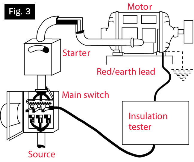
The insulation resistance tester (or megohmmeter), generally known by its trade name Megger, can provide critical information regarding the condition of motor insulation. In an industrial facility, the recommended procedure is to perform periodic tests and record the results so damaging trends can be detected and corrected to prevent an outage and extensive downtime.
The insulation resistance tester resembles a conventional ohmmeter. But rather than the typical three-volt test voltage derived from an internal battery and present at the probes, the Megger provides a much higher voltage applied for a proscribed length of time. The leakage current through insulation, expressed as resistance, is displayed so it can be graphed. This test may take place on installed or on-the-reel cable, tools, appliances, transformers, power distribution subsystems, capacitors, motors and any type of electrical equipment or wiring.
The test may be non-destructive, for in-service equipment, or prolonged at elevated voltage to test prototypes to the point of destruction. A bit of a learning curve is involved in using the Megger. The correct settings, connection procedures, test durations and safety precautions must be implemented to avoid damaging the equipment or electrocuting the operator or coworkers.
The motor under test must be powered down and disconnected from all equipment and wiring that’s not to be included in the test. Besides invalidating the test, such extraneous equipment could be damaged by the applied voltage. Additionally, unsuspecting individuals could be exposed to hazardous high voltages.
All wiring and equipment has an inherent amount of capacitance, which is generally significant in large motors. Because the equipment is in effect a storage capacitor, it’s essential that lingering electrical energy be discharged before and after each test. To do this, shunt the relevant conductor(s) to ground and to each other before reconnecting the power source. The unit should be discharged at least four times as long as the test voltage was applied.
The Megger is capable of applying different voltages, and the level should be coordinated with the type of equipment under test and the scope of the inquiry. The test generally applies between 100 and 5,000 V or more. A protocol involving voltage level, time duration, intervals between tests and connection methods must be composed, taking into account the type and size of the equipment, its value and role in the production process and other factors.
Motor testing equipment
Newer more contemporary instruments make testing even easier. For instance, test equipment such as Fluke’s 438-II Power Quality and Motor Analyzer uses algorithms to analyze not only three-phase power quality but also torque, efficiency and speed to determine system performance and detect overloaded conditions, eliminating the need for motor load sensors.
It provides analysis data for both the electrical and mechanical characteristics of the motor while in operation. Using proprietary algorithms, the 438-II measures the three-phase current and voltage waveforms and compares them against rated specifications to calculate motor mechanical performance. The analysis is presented in simple readouts, making it easy to gauge the operating performance and determine if adjustments are needed before failures cause an operational shut down.
The analyzer also provides measurements to determine a motor’s efficiency (for example, the conversion of electrical energy to mechanical torque) and mechanical power under operating load conditions. These measures allow for determining the motor’s in-service operating power compared to its rated power to see if the motor is operating in overloaded condition or, conversely, if it’s oversized for the application, energy may be wasted and operating cost increased.
Other developments include integrating multiple instrument functions into one unit. For instance, a new thermal imaging clamp-on ammeter from FLIR has a built-in infrared camera, which gives the user a visual indication of temperature differences and thermal anomalies.
NAVIGATE ELECTRICAL TROUBLESHOOTING FOR YOUR FACILITY
As Murphy’s Law would predict, electrical control system issues usually happen with the worst possible timing. It’s wise to be prepared with a troubleshooting plan. Often, we are quick to jump directly into fixing a problem when, in fact, it would benefit us to be methodical with our process. Here, we share a troubleshooting process that can help you navigate electrical troubleshooting for your facility.
Gather Information. The first step of any electrical system troubleshooting exercise involves gathering as much information about the problem as possible. Instead of immediately diving in and haphazardly attempting anything to get the equipment running, first step back and determine how is the equipment supposed to operate, what technical documentation is available for the equipment, and is there someone familiar with similar equipment who may have experienced this same issue.
Understand the malfunction and the role the malfunctioning equipment plays within the entire process. When you understand how the equipment and process is supposed to work, you can better understand what part of it is not functioning correctly.
Identify what can be measured so that you can identify items that are outside the acceptable range. For example, are there voltage readings or temperature readings that would help you evaluate the source of the problem?
Identify the source of the problem using available data and analytical tools to isolate the defective component. This could involve isolating components and evaluating their circuit parameters or isolating the circuits by group when dealing with a complicated circuit.
Correct/repair the damaged component.
Verify the repair after completion. Once the repair has been performed, start the system to ensure it now runs as required. This is important because there may have been other underlying problems. For example, there may be an issue with a circuit causing a fuse to blow (such as a shorted electrical connection). If this is the case, additional troubleshooting will be required.
Perform root cause analysis to determine what really caused the problem. Since one of the objectives of troubleshooting is to ensure the problem doesn’t reoccur, it is important to determine what really caused the malfunction and take action to ensure a permanent solution is found.
As you begin your troubleshooting, it may feel that it takes more time to go through a full process. But, in the end, it will save time when you are able to isolate entire components from the process. If troubleshooting becomes too frustrating, ask for help. Sometimes bringing in a fresh set of eyes can more quickly uncover what you have been missing. Even if your objective is to pull in an outside resource, following your own troubleshooting plan will speed the process because you will be able to provide the detailed information to those you contract to help.
Troubleshooting an electrical system fault can be a challenging, but ultimately rewarding, task. It’s exciting to see your efforts work out. Good Luck!
CALL US NOW :
(323) 609-8250
or
LEAVE US A MESSAGE AND WE WILL GET BACK TO YOU SHORTLY