Circuit breakers and transformers are two of the most common components in the power system. Catastrophic failure of these components will result in high cost associated with the loss of load and component replacement. Preventive maintenance may reduce these costs by extending the components’ lifetime and increasing availability. However, too much maintenance may be costly while too little maintenance may result in catastrophic failure. Probabilistic models that will include the effects of maintenance on reliability are needed to perform cost benefit analysis and arrive at an optimal maintenance strategy. A probabilistic maintenance model introduced earlier for power transformer is proposed for circuit breaker uses in this paper. The model is based on data coming from a study of deterioration process, maintenance tasks, and inspection tests for circuit breakers.
Safety Considerations
Warning: Only qualified electrical personnel familiar with the equipment, its operation and the associated hazards should be permitted to work on switchboards and switchgear. Always be certain that the primary and secondary circuits are de-energized before attempting any testing or maintenance.
General Visual and Mechanical Inspection of Switchgear
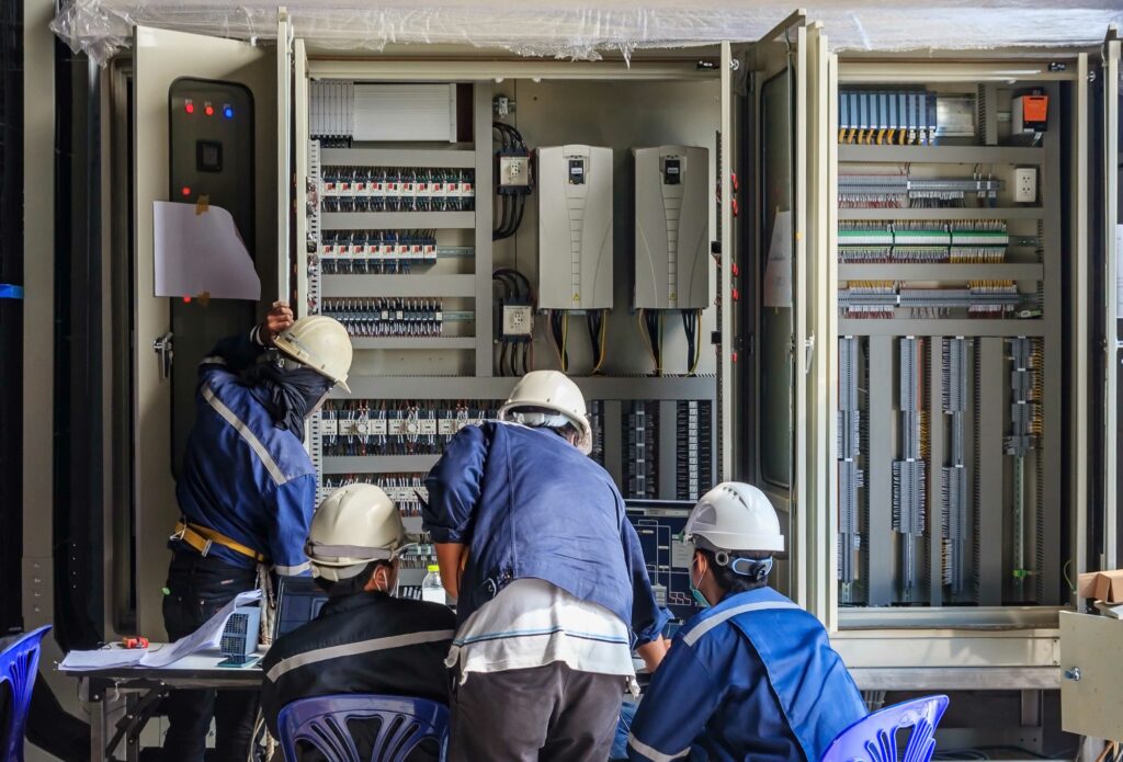
Switchgear should be inspected for proper anchorage, alignment, grounding and required clearances.
Switchgear should be inspected for proper anchorage, alignment, grounding and required clearances. Photo: General Electric.
- Inspect the physical, electrical, and mechanical condition of switchgear or switchboard, including its anchorage, alignment, grounding and required clearances. When performing acceptance testing, verify that the equipment nameplate data matches project drawings and specifications. This is important because switchboards are designed and rated for specific applications and should not be used otherwise, unless explicitly approved by the manufacturer.
- The unit should be clean and all shipping braces, loose parts, and documentation shipped inside the cubicles removed. Keep all documentation in a safe location for maintenance personnel in the future while loose parts and switchgear tools should be safely stored outside of the enclosure for easy access. When performing maintenance programs, clean the assembly using industry accepted methods of cleaning.
3.) For initial acceptance, verify that fuse and/or circuit breaker sizes, types, and protective settings match the project drawings and coordination study. Circuit breaker’s equipped with microprocessor-communication packages should be programmed with the proper digital address. All instrument transformer current and voltage ratios should also correspond to project drawings.
Moisture and Corona Inspections for Switchgear and Switchboards
If corona occurs in switchgear assemblies, it is usually localized in thin air gaps that exist between a high-voltage bus bar and its adjacent insulation or between two adjacent insulating members. Corona might also form around bolt heads or other sharp projections that are not properly insulated or shielded. Corona in low-voltage switchgear is practically nonexistent.
1.) Inspect for evidence of moisture or corona when performing maintenance inspections. On outdoor assemblies, roof or wall seams should be checked for evidence of leakage, and any leaking seams should be sealed with weatherproof caulk.
Prolonged leakage can be identified by rust or water marks on surfaces adjacent to and below leaky seams. The assembly base should be checked for openings that could permit water to drain into the interior, and any such openings should be caulked or grouted. Larger openings should be sealed to prevent rodent intrusion.
- All interior and exterior lighting should be checked for proper operation. It is essential for personnel safety that the area be well lit at all times in case of emergency response and other security reasons.
Circuit Breaker and Switch Tests for Switchgear and Switchboards
It’s essential that circuit breakers be tested and maintained to ensure proper operation during electrical faults.
It’s essential that circuit breakers be tested and maintained to ensure proper operation during electrical faults. Photo: Vacuum Interrupter Testing
The procedure for the inspection/testing of circuit breakers and switches is beyond the scope of this guide as each type and voltage class has its own procedure. Conduct electrical tests on circuit breakers in accordance with ANSI/NETA Section 7. Where applicable, testing of circuit breakers generally include:
Visual/Mechanical Inspection
Insulation Resistance
Dielectric Withstand
Contact/Pole Resistance
Electrical Operations
Vacuum Integrity
Power/Dissipation Factor
Protective Devices and Instrument Transformers
Results of electrical tests on circuit breakers and switches should be in accordance with ANSI/NETA Section 7.
Minimum voltage test
This test is often neglected even though it is specified and recommended in international standards. The test objective is to make sure that the breaker can operate at the lowest voltage level provided by the station battery during a power outage. The test is performed by applying the lowest specified operating voltage and verifying that the breaker operates within specified parameters. The standard test voltages are 85% and 70% of nominal voltage for close and open operations respectively.
Minimum voltage required to operate the breaker
This test, which should not be confused with the minimum voltage test just described, determines the minimum voltage at which the breaker is able to operate. It is a measure of how much force is needed to move the coil armature. This test is not concerned with contact timing parameters, only whether the breaker operates or not. The test starts by sending a control pulse at a low voltage to the breaker. If the breaker doesn’t operate, the voltage is increased by, say, 5 V and the test is repeated. This procedure is continued, with gradually increasing voltage, until the breaker eventually operates. The voltage at which this occurs is recorded and, if the test is repeated next time the breaker is maintained, a comparison between the old and new figures will indicate whether significant changes have occurred.
Vibration testing
Vibration testing is based on the premise that all mechanical motion in equipment produces vibrations, and that by measuring them and comparing the result with the results of previous tests (known data), the condition of the equipment in question can be evaluated.
The easiest parameter to measure is the total vibration level. If it exceeds a specified value, the equipment is deemed to be in the fault or at-risk zone. For all types of vibration testing, a reference level must have been previously measured on equipment known to be fault free. All measurements on the equipment tested are then related to this reference signature in order to determine whether the measured vibration level is “normal” or whether it indicates the presence of faults.
Vibration analysis is a non-invasive test technique that uses an acceleration sensor with no moving parts. The breaker can stay in service during the test; an open-close operation is all that is required for the measurement. First-trip operation can be different from the second and third because of corrosion and other metal-to-metal contact issues. Vibration is an excellent method to capture the data about the first operation after the breaker has spent a long time in the same position.
The analysis of vibration data involves comparing the latest results with the reference. Vibration measurement can detect faults that are barely noticeable using other conventional methods. However, if data such as contact timing, travel curve, coil current and voltage are available in addition to the vibration data, even more precise condition assessment is possible.
Vacuum bottle test
Vacuum bottles in vacuum circuit breakers are tested with high voltage AC or DC to confirm the integrity of the vacuum. The electrical behaviour of the vacuum in the bottle is identical for AC and DC. The main difference in using DC and AC is that AC measurements are influenced by capacitance. The resistive current component is typically between 100 and 1,000 times smaller than the capacitive current component, and the resistive component is therefore difficult to distinguish when testing with AC. As a result, AC requires much heavier equipment for testing compared to DC test instruments.
Both the DC and the AC methods are detailed in standards ANSI/IEEE 37.20.2-1987, IEC 694 or ANSI C37.06.
Synchronized switching
In order to test the function of a controlled switching device one or more currents from current transformers and reference voltages from voltage transformers are recorded, along with controller output signals, while issuing an open or close command. Details of the test set up depend on the test instrumentation, as well as the available voltage and current sources.
SF6 leakage
SF6 leakage is one of the most common problems with circuit breakers. The leakage can occur in any part of the breaker where two components are joined, such as valve fittings, bushings and flanges. In rare cases, SF6 can also leak straight through the aluminium as a result of poor casting. Leaks can be found by using gas leak detectors (sniffers) or thermal imaging.
Humidity test
As humidity can cause corrosion and flashovers inside a breaker, it is important to verify that the moisture content inside an SF6 breaker is minimal. This is done by venting a small amount of SF6 gas from the breaker through a moisture analyser, which will determine the moisture content of the gas.
Air pressure test
Air pressure testing is carried out on air-blast breakers. Pressure level, pressure drop rate and airflow are measured during various operations. The blocking pressure that will block the operation of the breaker in the event of very low pressure may also be measured.
Conclusions
Breakers are complicated, mechanically sophisticated devices that require periodic adjustment. Sometimes a technician can see the need for these adjustments with a visual inspection, and the problem can be solved without testing. However, with most circuit breaker issues, testing will be required. When maintaining a circuit breaker, technicians should start with timing and motion measurements. In fact, if that technician only has time for a single measurement, that measurement should be timing.
Electrical power network growth and asset development requires that all available technologies be implemented to ensure reliable electricity supply. New technology for circuit breaker testing offers a more cost efficient test procedure and, since it allows both sides of the breaker to be grounded during testing, it ensures safety for key employees in accordance to national laws, standards and social partners demands.
Circuit breaker testing
Circuit breakers perform three main tasks: When closed, they must conduct the current as effectively as possible. When open, they must insulate the contacts from one another as effectively as possible. In the event of a malfunction, they must disconnect the fault current as quickly and reliably as possible, thereby protecting all subsequent equipment. In the US market and regions of frequent earthquakes, the most popular high-voltage circuit breakers are “dead tank” units, whereas in central Europe “live tank” breakers are standard. In other parts of the world, both circuit breaker types can be found.
In the worst case, a circuit breaker might stand still for several years, but then, in the event of a malfunction, it has to disconnect fault currents of many kiloamps reliably within just a few milliseconds. Typical faults that occur on circuit breakers are short circuits in the coils, incorrect behavior, for example due to worn contacts, as well as damage/wear to the mechanical connections or the insulation material. Therefore, circuit breakers need to be regularly and carefully tested.
Circuit breaker testing typically focuses on performing motion and time measurements on the units. However, our testing solutions have revolutionized circuit breaker testing. The testing solutions we offer include systems that can supply power during the testing process and are capable of measuring the micro-ohm resistance across the closed contacts. Performing the tests without use of the station battery greatly increases safety throughout the testing process.